Architectural Millwork · October 16, 2026 · 12 min read
CNC-Slotted Millwork Panels: 7 Details to Settle Before Cutting
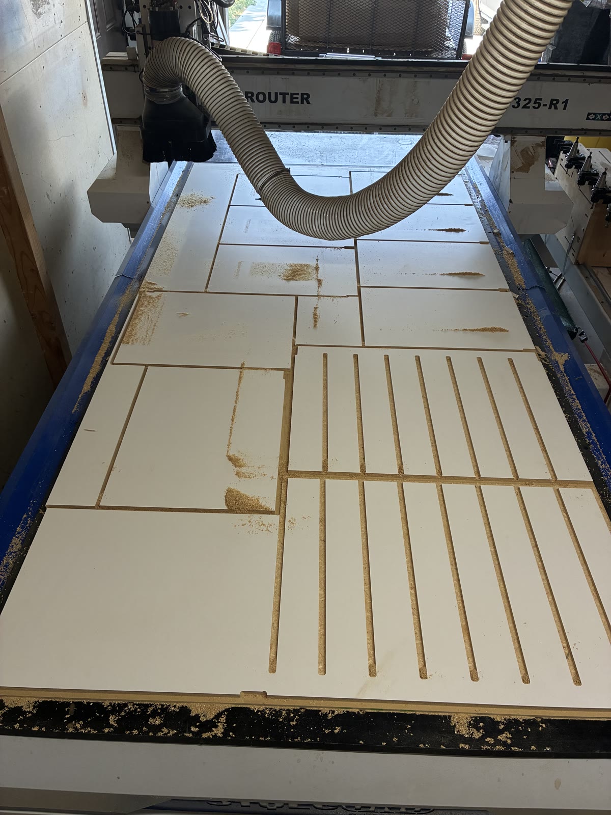
A CNC-routed slotted panel looks simple on a drawing. Specify the panel dimensions, add a series of parallel openings, and send the file to the router.
But seven details determine whether that panel is actually ready for fabrication: its intended function, material, slot geometry, remaining material between openings, mounting conditions, machining sequence, and edge finish.
Get those right and the CNC can reproduce the pattern accurately across multiple panels.
Get them wrong and a straightforward decorative detail becomes a shop problem—or a field problem that doesn't appear until installation.
For architects, designers, GCs, and other millwork shops, the objective is to resolve those details before material gets cut.
What Is a CNC-Slotted Millwork Panel?
A CNC-slotted panel is a sheet-material component with a series of openings machined into its face.
Depending on the specification, these panels may serve as decorative screens, equipment surrounds, ventilation openings, access-panel components, or other architectural details.
The CNC controls the location, length, width, and spacing of the openings.
That repeatability is valuable when several panels need to match or when the pattern must align with adjacent casework.
The fabrication method, however, does not establish how the finished panel will perform.
A panel intended only as a decorative feature is different from one expected to move a specified volume of air.
That distinction needs to be established before fabrication begins.
1. Define What the Slots Are Supposed to Do
The first question is not how wide the slots should be.
It is why they are there.
A decorative panel may be designed primarily around appearance, alignment, and finish quality.
A ventilation panel also needs to account for airflow requirements and whatever equipment, filter, grille, or assembly sits behind it.
An acoustical panel may require testing or a specified backing assembly to achieve a particular performance.
Those are different design problems.
A CNC router can reproduce the same slot pattern for all three applications, but that does not make the panels interchangeable.
For mechanical applications, the designer or mechanical trade should establish the required performance.
The millwork fabricator can then coordinate the physical dimensions and determine whether the specified panel is practical to manufacture.
2. Specify the Actual Panel Material
"White panel" is not a complete material specification.
Commercial millwork can involve TFL-faced particleboard, MDF, plywood, high-pressure laminate assemblies, veneered panels, or other engineered sheet products.
Those materials do not necessarily machine or finish the same way.
A through-cut slot exposes the panel's internal material, which may look and behave considerably differently from its factory-finished face.
On a laminated particleboard panel, for example, the finished face may be smooth and uniform while the slot exposes a comparatively rough core.
That can create two separate finishing questions:
What should the face look like?
What should the inside surfaces of the slots look like?
The project specification and approved submittal should identify the substrate, facing, thickness and finish before fabrication. AWI’s materials standard addresses material selection and its relationship to appearance and performance within its applicable scope. AWI materials standard scope

3. Establish Slot Geometry Before Programming
A slotted-panel drawing needs more than a visual pattern.
The fabricator needs the dimensions that actually control the machining.
| Dimension | What needs to be established |
|---|---|
| Finished panel size | Overall width and height |
| Panel thickness | Specified material and actual stock thickness |
| Slot width | Finished opening width |
| Slot length | Overall end-to-end dimension |
| Slot spacing | Clear distance between slots or center-to-center pitch |
| Pattern location | Distance from panel edges to the first and last openings |
| End geometry | Rounded ends, squared ends, or another specified detail |
| Orientation | Direction of slots relative to panel grain or architectural layout |
| Tolerances | Permitted variation in finished geometry |
| Finish | Treatment required on cut edges and exposed core |
One important constraint is the router bit itself.
A standard cylindrical end mill produces a rounded internal end when it follows a centerline slotting path. The radius corresponds to the cutter geometry.
If the design requires perfectly square internal ends, that may require a different operation or an alternative construction method.
That is not a problem.
It just needs to be decided before the shop drawings are approved.
4. Leave Enough Material Between the Openings
Every slot removes material from the panel.
As the slots get longer or closer together, the remaining strips of material become narrower.
Those remaining strips are often called webs.
Their dimensions affect how the panel behaves during machining, handling, finishing, transportation, and installation.
A pattern that looks proportionally correct on a rendering can become difficult to manufacture if the webs are too narrow for the material and unsupported span.
There is no universal minimum web dimension that applies to every slotted panel.
The practical limit depends on panel thickness, material construction, slot length, support locations, mounting method, and how the finished component will be used.
For production planning, we want to know whether the remaining material will stay adequately supported throughout the entire process.
That includes the time between removing the part from the CNC bed and installing it in the finished assembly.
A panel that survives machining but breaks during handling is not an efficient fabrication method.
5. Coordinate What Goes Behind the Panel
The visible slots may only occupy a small portion of the overall millwork assembly.
The space behind them can be more important.
Depending on the application, there may be equipment, structural framing, mounting cleats, filters, ducts, wiring, or other concealed components.
Those elements can influence where the slots should be located.
They may also obstruct the openings.
For a decorative panel, that might only create an unwanted visual condition.
For a ventilation application, obstruction becomes a performance issue.
Greenheck's published louver guidance distinguishes the overall face area from the available free area and explains why airflow requirements cannot be established simply by assuming a fixed percentage of open space. Greenheck louver performance guidance
That louver guidance illustrates a coordination principle; it is not a performance test or certification of a slotted wood panel.
A panel can have a particular amount of geometric opening area without being a verified ventilation product.
A Simple Open-Area Example
Suppose a drawing calls for ten slots, each nominally ¼ inch wide and 12 inches long.
Using a rectangular approximation:
10 × 0.25 × 12 = 30 square inches of opening area.
That is a useful preliminary geometric calculation.
It is not an airflow rating.
Rounded slot ends change the actual area slightly. Backing, equipment, screens, and the geometry of the air path can further affect flow resistance.
If a project has a required CFM, pressure drop, or other mechanical performance requirement, that information should come from the mechanical design—not from the cabinet shop estimating airflow from the slot count.
6. Plan the CNC Toolpaths Around Material Support
Repeated slots introduce a machining problem that differs from ordinary cabinet-part cutting.
On a typical cabinet side, many operations can be completed while the sheet remains largely intact.
A slotted panel gradually loses material and support as the openings are machined.
Depending on how the part is held, through-cut slots may also reduce the effectiveness of vacuum hold-down.
That means the sequence of operations matters.
We already covered the broader subject of cut sequencing in our earlier article, CNC Nesting for Cabinet Parts: How We Sequence Cuts to Reduce Waste and Rework.
Slotted panels add a more specific question:
How do we machine every opening while keeping the remaining panel stable?
That may influence which openings get cut first, where the sheet is supported, how the interior waste is controlled, and when the outside perimeter is machined.

Tool selection is also important.
The cutter has to be appropriate for the material, slot width, cutting depth, and finish requirements.
For double-sided laminated wood composites, LMT Onsrud manufactures compression cutters specifically intended to improve cutting performance and finish quality. This manufacturer example does not identify the cutter used in the photographs. It shows why cutter geometry should be chosen for the actual material rather than treating all router bits as interchangeable. LMT Onsrud compression cutter example
There is another practical consideration: a cutter can produce a clean outside perimeter without necessarily being the best tool for machining every internal detail.
The operation determines the tooling.
Not the other way around.
7. Decide How the Exposed Slot Edges Will Be Finished
A clean CNC cut and a finished architectural surface are not always the same thing.
Through-cutting a laminated panel exposes the substrate.
Depending on the material and intended appearance, those edges may need sanding, sealing, coating, or another approved treatment.
The finishing requirement should be resolved before programming because it can affect material selection and the practical slot width.
A narrow opening may be easy to machine but difficult to sand or finish consistently afterward.
That creates a familiar problem in custom millwork:
The design is technically machinable, but the finishing process makes it impractical.
For exposed architectural work, the correct comparison is not simply how long the router takes to produce the pattern.
It is the total time required to manufacture a component that meets the specified appearance.
Machining time is only one part of finished-component cost.
What We Want to See on the Shop Drawings
Before releasing a slotted-panel component to production, the important questions should already have answers.
| Coordination item | Question to resolve | Risk if missed |
|---|---|---|
| Intended function | Decorative, ventilation, acoustic, or another application? | Fabricated geometry may not meet functional requirements |
| Material | Exact substrate, facing, and thickness? | Inconsistent machining or finish |
| Slot layout | Width, length, spacing, edge offsets, and orientation? | Pattern does not match design intent |
| Cutter geometry | Are rounded ends acceptable? | Unexpected appearance or additional machining |
| Structural support | Are webs, margins, and mounting conditions adequate? | Damage during production or installation |
| Concealed conditions | What sits behind the openings? | Obstruction or mounting conflicts |
| Edge finish | Is exposed core acceptable? | Additional finishing or rejection |
| Production quantity | Are multiple matching panels required? | Inconsistent patterns or inefficient setup |
| Approval | Who signs off on geometry and material? | Unnecessary remake or field modification |
This is the point where the fabrication conversation should happen.
The architect establishes design intent and applicable performance requirements.
The GC coordinates the surrounding work and project schedule.
The relevant mechanical or specialty trade addresses system performance when required.
The millwork subcontractor determines how to manufacture the approved geometry accurately and consistently.
That division of responsibility produces a much cleaner handoff.
Where CNC Fabrication Adds Value
A shop with a CNC router can reproduce complex panel geometry without laying out each opening by hand.
That is particularly useful when the same slot pattern appears across several different-sized components.
A panel might change width or height while the slot geometry remains consistent.
The digital file can preserve those relationships and make revisions easier to control.
The CNC also provides an efficient way to produce a sample panel before committing to the complete package.
For unfamiliar materials or detailed profiles, a sample can reveal issues with edge quality, slot spacing, finish preparation, or material support that are not obvious in CAD.
A good sample is not just something to show the architect.
It is an opportunity to prove the fabrication method.
That is a significant advantage for custom architectural millwork, where the objective is often to produce a relatively small number of unique components accurately rather than manufacture thousands of identical parts.
Frequently Asked Questions About CNC-Slotted Millwork Panels
Can CNC routers cut ventilation openings in cabinet panels?
Yes. CNC routers can machine repeated openings in suitable sheet materials. However, the ability to cut those openings does not establish that the finished assembly meets ventilation requirements. Required airflow and equipment performance should be coordinated with the appropriate mechanical designer or trade.
Why do CNC-routed slots usually have rounded ends?
Because a cylindrical router bit naturally produces a radius at the end of an internal slot. The exact geometry depends on the cutter and toolpath. Square-ended openings may require additional machining or a different fabrication method.
Can slots be machined in melamine or TFL panels?
Yes. Laminated panels can be CNC-machined using appropriate tooling and cutting strategies. The exposed substrate inside the slots still needs to be evaluated for appearance and any required finishing.
Is there a standard minimum distance between slots?
Not one that can safely be applied to every material and application. The required web width depends on material properties, thickness, slot length, support, load, and the intended use of the panel. Critical structural or performance requirements should be established by the responsible designer.
Is a panel with more open area automatically better for ventilation?
No. Open area is one factor in airflow performance, but pressure drop and the overall geometry of the assembly also matter. Greenheck's technical guidance specifically cautions against selecting louvers solely from assumed free-area percentages. Greenheck louver performance guidance
Can slotted panels be considered acoustical panels?
Only when the specified construction has appropriate evidence supporting the claimed acoustical performance. A visible slot pattern alone does not establish an acoustic rating.
What information should a GC or designer send for CNC-slotted panel fabrication?
Provide the relevant drawings, finished panel dimensions, material specifications, slot layout, finish requirements, mounting details, quantity, approval requirements, and required delivery date. Include performance requirements and supporting details whenever the openings serve a functional purpose.
Can 3D Cabinetry fabricate specialty CNC components for another millwork shop?
We can review CNC component-production and architectural millwork scopes independently of full cabinet installation when the project is a suitable fit. Send the drawings, material specifications, quantities, and schedule so we can determine whether the work is appropriate for our equipment and production process.
Resolve the Detail Before Fabrication
A slotted architectural panel is a useful example of where digital fabrication and traditional shop judgment meet.
The CNC handles repetitive geometry accurately.
The fabricator still has to determine whether the material, slot layout, toolpath, support, and finish requirements will produce an acceptable component.
For architects, GCs, and other trades, the best opportunity to control those details is before fabrication—not after the first panel comes off the machine.
At 3D Cabinetry & Custom Renovations, we use CNC fabrication as part of our broader approach to custom cabinetry, commercial casework, and architectural millwork.
Our objective is to turn coordinated drawings into accurate parts while keeping material selection, fabrication, finishing, and installation requirements connected.
For commercial casework, architectural millwork, custom CNC fabrication, or component-production opportunities in Boise and suitable nearby markets, send us the plans, material specifications, quantities, and required delivery date.
We'll review the scope and determine how the project fits our shop capabilities.